How to Size a VFD Properly: Variable Frequency Drive Sizing Guide for Industrial Electric Motors
Learn how to size a VFD properly for industrial electric motors. This variable frequency drive sizing guide explains full-load amps (FLA), torque requirements, overload ratings, environmental factors, and motor controller selection best practices.
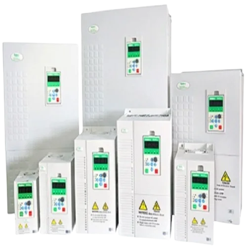
Variable Frequency Drives (VFDs) have become a critical component in modern industrial facilities, enabling energy-efficient motor control, improved process automation, and reduced mechanical wear. However, one of the most common mistakes in industrial automation projects is selecting a VFD based solely on motor horsepower.
Proper VFD sizing requires a comprehensive evaluation of motor current, torque demands, duty cycles, environmental conditions, overload requirements, and power quality considerations. An incorrectly sized drive can lead to nuisance trips, reduced equipment lifespan, poor process performance, and unnecessary operational costs.
For manufacturers, engineers, and facility managers across Kenya and East Africa, understanding how to size a VFD correctly is essential for ensuring reliable and efficient motor operation.
Why Proper VFD Sizing Matters
Proper VFD sizing ensures reliable motor performance, maximizes energy efficiency, and prevents drive failures caused by overload, overheating, or incorrect application selection. Choosing a VFD based only on horsepower can result in undersized or oversized systems that negatively affect productivity and equipment lifespan.
A correctly sized VFD provides:
- Stable motor operation
- Improved process control
- Reduced maintenance costs
- Longer equipment life
- Better energy efficiency
- Enhanced system reliability
An undersized VFD may continuously trip during peak loads, while an oversized unit increases capital costs without delivering proportional benefits.
Industrial facilities looking to optimize motor control systems can explore solutions through the Paneltech Systems Products Page.
Understanding the Basic Function of a VFD
A Variable Frequency Drive controls motor speed and torque by adjusting the frequency and voltage supplied to the motor. This allows motors to operate at the exact speed required by the process rather than running continuously at full speed. Proper sizing ensures the drive can safely handle the motor's operating demands.
A VFD consists of three main sections:
Rectifier
Converts incoming AC power into DC power.
DC Bus
Stores and smooths electrical energy.
Inverter
Converts DC power back into variable-frequency AC power for the motor.
The drive continuously regulates motor output to match process requirements, improving efficiency and reducing energy waste.
Learn more about industrial automation and electrical engineering solutions on the Paneltech Systems Homepage.
Step 1: Start with Motor Nameplate Data
The motor nameplate provides the most important information for VFD sizing, including voltage, full-load current, horsepower, frequency, and service factor. Full-load current (FLA) is generally more important than horsepower when selecting a VFD.
Typical nameplate information includes:
| Parameter | Example |
|---|---|
| Power Rating | 30 kW |
| Horsepower | 40 HP |
| Voltage | 400V |
| Frequency | 50Hz |
| Full Load Amps (FLA) | 58A |
| Speed | 1470 RPM |
| Power Factor | 0.86 |
Many engineers mistakenly size drives solely by horsepower.
However, VFD manufacturers primarily rate drives based on continuous output current, making FLA the most critical parameter.
Step 2: Use Full Load Amps (FLA) Instead of Horsepower
Full-load amps (FLA) should be the primary sizing parameter because motor current determines the actual electrical load the VFD must support. Motors with identical horsepower ratings can have different current requirements depending on efficiency, design, and operating conditions.
For example:
| Motor | HP | Voltage | FLA |
|---|---|---|---|
| Motor A | 30 HP | 400V | 42A |
| Motor B | 30 HP | 400V | 50A |
Despite having the same horsepower, Motor B requires a larger drive due to its higher current demand.
Always verify:
- Motor nameplate current
- Drive continuous current rating
- Overload capability
This approach ensures accurate industrial motor controller selection.
Step 3: Evaluate Load Type and Torque Requirements
Different applications require different torque characteristics, making load analysis a critical step in VFD sizing. Constant torque applications typically require larger drives than variable torque applications because they place greater demand on the motor throughout operation.
Variable Torque Loads
Examples include:
- Centrifugal pumps
- Ventilation fans
- HVAC systems
- Cooling towers
Characteristics:
- Torque decreases as speed decreases
- Lower current demand
- Smaller drive sizing possible
Constant Torque Loads
Examples include:
- Conveyors
- Mixers
- Crushers
- Extruders
Characteristics:
- Full torque required across operating speeds
- Higher current demand
- Larger VFD capacity required
Industrial automation projects often require detailed torque analysis before final drive selection.
Explore automation solutions via the VFD Drive Solutions Page.
Step 4: Consider Overload Capacity
VFDs must be sized according to expected overload conditions because many industrial processes require temporary current levels above normal operating values. Drives with insufficient overload ratings may trip during startup or production surges.
Typical overload classifications include:
| Duty Type | Overload Rating |
|---|---|
| Normal Duty | 110% for 60 seconds |
| Heavy Duty | 150% for 60 seconds |
| Extra Heavy Duty | 180%–200% |
Heavy-duty applications commonly include:
- Conveyors
- Compressors
- Crushers
- Hoists
- Material handling equipment
Choosing the correct overload class prevents nuisance shutdowns and production interruptions.
Step 5: Account for Ambient Temperature
Ambient temperature directly affects VFD performance because excessive heat reduces cooling efficiency and may require drive derating. Facilities operating in high-temperature environments often need larger VFDs to maintain reliable operation.
In Kenya, temperature conditions vary considerably:
Nairobi
Moderate ambient temperatures generally support standard VFD ratings.
Mombasa
Higher temperatures and humidity increase thermal stress.
Industrial Regions
Factories with poor ventilation may experience elevated enclosure temperatures.
Manufacturers often specify derating factors above:
- 40°C ambient temperature
- 1000m altitude
Ignoring temperature effects can significantly reduce drive lifespan.
Step 6: Evaluate Environmental Conditions
Environmental conditions such as dust, humidity, vibration, and corrosive contaminants significantly influence VFD selection and enclosure requirements. Proper protection ensures long-term reliability and compliance with industrial standards.
Coastal Environments
Facilities in Mombasa often require:
- IP65-rated enclosures
- Corrosion-resistant components
- Enhanced ventilation systems
Dusty Industrial Areas
Factories in parts of the Rift Valley may require:
- IP54 or IP65 protection
- Filtered cooling systems
- Sealed control panels
Environmental protection is particularly important for maintaining reliable industrial automation systems.
Paneltech engineers design solutions tailored to local operating conditions through the Paneltech Engineering Services Page.
Step 7: Check Supply Voltage Compatibility
The VFD input voltage must match the available electrical supply and motor requirements to ensure safe and efficient operation. Voltage mismatches can damage equipment and cause drive faults.
Common industrial voltages in Kenya include:
| Supply Voltage | Typical Application |
|---|---|
| 230V | Small commercial systems |
| 400V | Industrial facilities |
| 415V | Manufacturing plants |
| 690V | Large industrial motors |
Always verify:
- Utility voltage
- Motor voltage rating
- VFD input specifications
Voltage compatibility is essential for reliable operation.
Step 8: Consider Harmonics and Power Quality
Harmonics generated by VFDs can affect electrical system performance and should be considered during drive selection, particularly in facilities with multiple drives. Harmonic mitigation improves power quality and protects sensitive equipment.
Potential issues include:
- Increased transformer heating
- Voltage distortion
- Nuisance tripping
- Reduced equipment lifespan
Mitigation methods include:
- Line reactors
- Harmonic filters
- Active harmonic correction
- Multi-pulse drive configurations
Facilities with extensive motor installations often combine VFD systems with power factor correction solutions.
Learn more about power quality optimization through APFC Panel Solutions.
Step 9: Plan for Future Expansion
Future capacity requirements should be considered during VFD selection to avoid costly upgrades as production demands increase. Strategic sizing allows facilities to accommodate growth while maintaining operational efficiency.
Questions to consider:
- Will production capacity increase?
- Will larger motors be installed later?
- Will automation systems expand?
- Are additional loads anticipated?
While excessive oversizing is not recommended, modest allowances for future growth can provide long-term value.
Common VFD Sizing Mistakes
Common VFD sizing mistakes include relying solely on horsepower ratings, ignoring overload requirements, overlooking environmental conditions, and failing to account for power quality issues. These errors often result in unreliable system performance and increased operating costs.
Frequent mistakes include:
Selecting by Horsepower Alone
Current ratings are more important.
Ignoring Torque Requirements
Heavy-duty loads require different sizing approaches.
Neglecting Environmental Conditions
Heat, humidity, and dust affect performance.
Overlooking Harmonics
Power quality issues can impact facility operations.
Failing to Review Duty Cycles
Intermittent and continuous loads have different requirements.
Avoiding these errors significantly improves system reliability.
System Specifications Table: Industrial VFD Selection Guide
| Parameter | Typical Specification |
|---|---|
| Rated Voltage | 380–415V AC |
| Frequency | 50Hz |
| Motor Type | Three-Phase AC Induction Motor |
| Power Range | 0.75kW – 500kW+ |
| Control Method | V/F, Sensorless Vector, Closed Loop |
| Overload Rating | 110%–200% |
| Protection Rating | IP20, IP54, IP65 |
| Communication Protocols | Modbus, Profibus, Ethernet/IP |
| Mounting Type | Panel Mounted / Floor Standing |
| Compliance Standards | IEC 61800, IEC 61439, BS EN Standards |
VFD Sizing and Compliance Requirements in Kenya
Industrial VFD installations in Kenya should comply with applicable EPRA requirements and internationally recognized IEC standards to ensure safety, reliability, and long-term performance. Compliance reduces operational risks and supports proper engineering practices.
Relevant standards include:
- IEC 61800 (Adjustable speed electrical power drive systems)
- IEC 61439 (Low-voltage switchgear assemblies)
- BS EN electrical standards
- EPRA electrical installation requirements
Manufacturers seeking compliant motor control solutions can explore products through the Paneltech Systems Product Portfolio and supporting components via Multispan Industrial Components and Rishabh Electrical Products.
Conclusion
Proper VFD sizing involves far more than matching a motor's horsepower rating. Engineers must evaluate full-load current, torque requirements, overload demands, environmental conditions, power quality considerations, and future operational needs.
A carefully selected VFD delivers superior energy efficiency, reliable motor control, reduced maintenance costs, and improved process performance. For manufacturers across Kenya and East Africa, accurate VFD sizing is one of the most important steps toward achieving successful industrial automation and long-term operational reliability.
Contact Paneltech Systems Ltd
Powering Kenya's Future with Reliable Electrical Solutions
Email: [email protected]
Phone: 0799 531765
Location: Nairobi, Kenya
Website: https://paneltechsystems.co.ke/
Our Specialized Services:
- Low Voltage (LV) Panels & APFC Panels
- VFD Drive Solutions & ATS / MTS Systems
- Solar Power & EV Charging Infrastructure
- Electrical Supplies & Engineering Consultations